Hop in and trim the outdrive all the way down then all the way up do not use the trailer switch. You should see a nice smooth resistance change with no jumping on the resistance change.

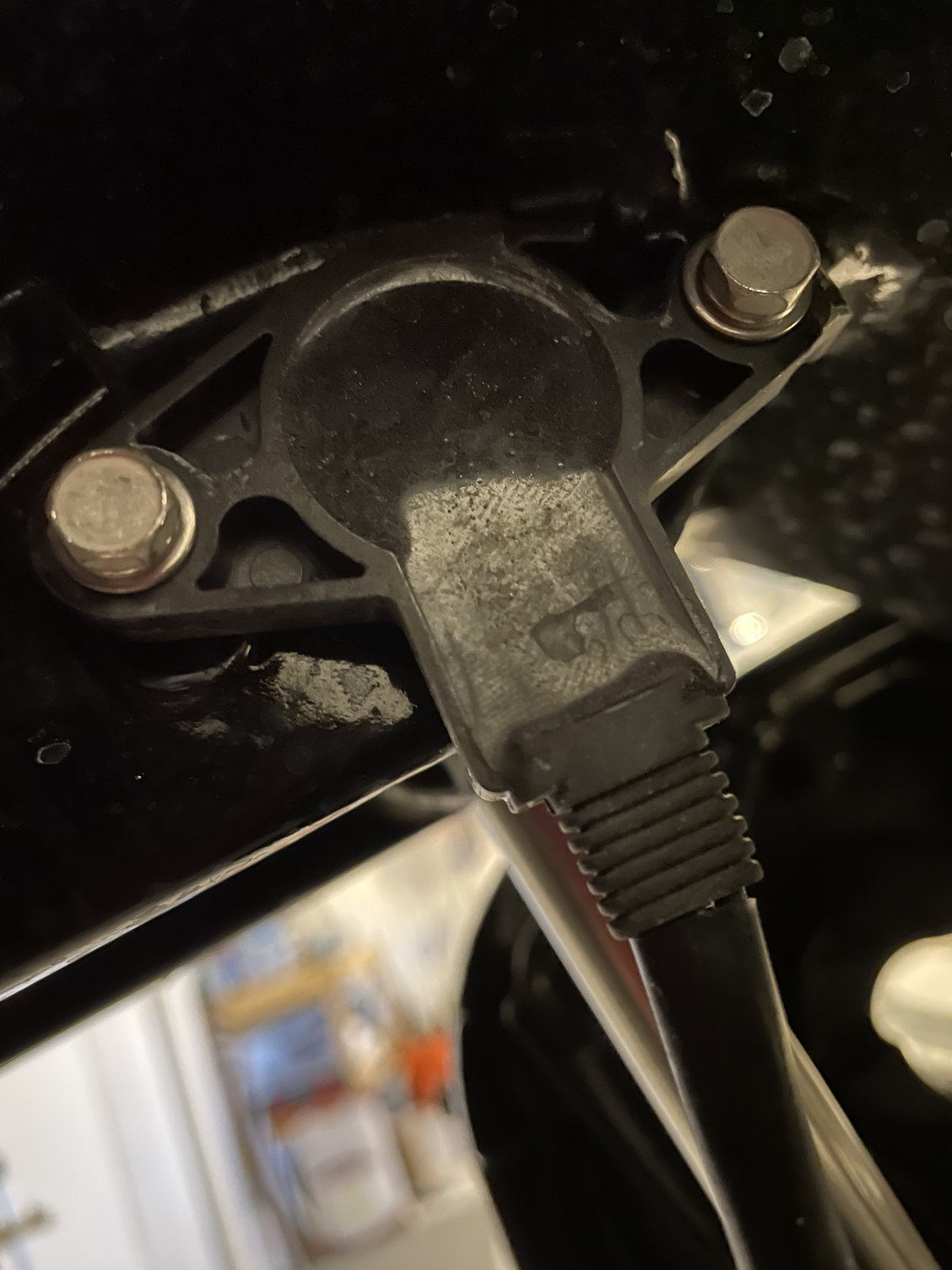
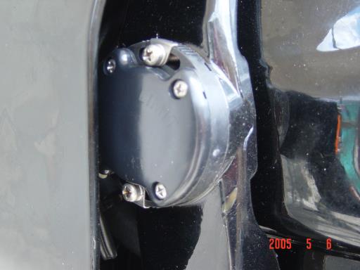
The Trim Limit Switch is mounted on the port side and the Trim Position Switch is mounted on the starboard side.
Mercury outboard trim sender adjustment. Hop in and trim the outdrive all the way down then all the way up do not use the trailer switch. Measure the center to center distance of the bolts that hold the trim cylinder on. It should be 21 34 inches.
If it is you are all set. If not you have to go through the adjustment procedure. 805320A1 TRIM SENDER AND TRIM LIMIT SWITCH KIT Page 8 of 10 11.
Turn ignition key to the RUN position. DO NOT START ENGINE. Rotate sender until needle is at bottom of arc on gauge.
Tighten trim position sender retaining screws and recheck gauge reading. Reconnect trim limit switch wires to trim pump harness. Secure wires in retainer with.
Make your adjustment with the full drive in the down position turn the sender in small increments until the trim gauge reads in the down position on your trim gauge Mercruiser trim sender adjustment is only concerned with showing the full down position not the up position. The steps are. 1 turn boat key to the on position 2 raise motor up to where you can see the trim sending unit 3 loosen the two screws on the trim sending unit so you can move it in its positioning slots 4 move it a little 5 lower the motor to the fully down position and go look at trim gauge needle and 6 repeat steps 2-5 until you have the trim sending unit positioned where the needle.
You loosen a screw or two on the sender and move the sender a bit and re-tighten the screws. After a little trial and error you should find the sweet spot postion for the sender. Trim and Tilt gauge adjustment.
Insert a tilt lock rod into the center hole of the transom brackets so that the tilttrim of the engine will only drop to that center point. Lower the engine and observe the gauge. This gives you a good idea which way and how far to adjust that tilt sender at the engine.
We occasionally have questions. To adjust this style you simply loosen the two screws and twist the sending unit until the gauge agrees with the trim position of the motor. With the motor trimmed fully down the trim gauge should be just dropping to its minimum position.
Trim Position Sender Adjustment 1. Place drive unit in full down position. Loosen trim position sender retaining screws.
Turn ignition key to RUN. Rotate sender housing in either direction until power trim gauge needle rests at bottom of green WC. Recheck instrument reading and turn ignition key OFF.
Finally figured out the problem. I guess when flushing the motor with the pull out hose in the cowling it pulled the trim sender wire a little bit to where it wasnt getting good contact. Plugged it back in and got a good firm click on the weather pack plug and everything seems to be working great.
Back up to 61mph and 5800 rpm wot. It is pretty easy to check. Basically all that the sending unit is - is a variable resistor.
You can just unplug the sender put an ohmmeter on the leads and vary the center shaft by roating it. You should see a nice smooth resistance change with no jumping on the resistance change. Trim limit switch adjustment help Post by AsLan7 Tue Mar 19 2019 125 am Crowncourier wrote.
Tue Mar 19 2019 120 am Ill take some pics and check the trim gauge when I get back in town later this week. Trim Tilt Gauge Sending Unit. Posted 03-13-2005 0434 PM ET US I bought a tilttrim indicator gauge today for 1999 at Boaters World.
The instructions say I must have a sending unit for the gauge to work. The guy at the check out counter said most newer outboards with trimtilt have a sending unit standard. Mercury 3 - 2 wire tilt trim conversion 1997 90 hp.
Tilttrim leaking between motor and pump. Trimtilt 115 Mariner 6. 1988 Meriner 75 tilt and trim problem.
Trimtilt 115 Mariner 6. 2003 75hp Merc Tilt Trim wiring. Mercury 850 Power TiltTrim.
Mecury 75 TiltTrim Problems. Mercury 850 tilttrim 1976 850 85 hp. 96 Mariner 75 trim motor.
Unit how to effectively trim your boat power trim is the hydraulic adjustment of your stern drive or outboard which will affect the direction of the bow trim down you will lower the bow and cut through the oncoming water his gauge may. Mercury Boat Trim Sender Assembly 859187A1 Optimax Outboard. 42 out of 5 stars 8.
Get it Wed Oct 13 - Fri Oct 15. WFLNHB Trim Sender Sensor Fit for MercuryMariner V-6 Digital Optimax. 25 out of 5 stars 3.
Get it Fri Oct 15 - Thu Oct 21. Optimax Trim Gauge Refer to Illustration 6 below 9. Locate the three 3 trim sender wires Blue Black and Yellow.
Unplug the bullet connectors and seal the engine connectors with two 2 Female Bullet Connector Caps and the Male Bullet Connector Cap removed in Step 3. If the Male Bullet. In Stock Only 7 left in stock.
Ships in 24 Hours Displaying availability for Choose A Location. Add to Cart Add to List. Replacing Your Trim Limit and Trim Position Senders Alphas and Bravos have two Trim Senders.
They are mounted on either side of the Gimbal Ring. One sender is for the Trim Gauge and the other sender is for the Trim Limit. The Trim Limit Switch is mounted on the port side and the Trim Position Switch is mounted on the starboard side.
The switches are prone to damage from water intrusion. Trim Sender for Mercury 90. I would like to install a trim sender on my new to me motor.
It is a 2004 Mercury 90hp 2-stroke with serial OT958205. I have looked everywhere and I cant find one for it. I know they have to make one for it Im just not sure which one it is.
Trim Limit Switch Adjustment. June 2016 in General Boating Discussions. Not the sender- that was not tricky at all but the limit switch.
Alpha one gen two. How do you do it. Ive read it is done by measurement of the rams and after raising it from fully down- but.
Yeah that didnt work. Trim In Angle Adjustment WARNING Boat operation with outboard trimmed to the full In trim angle not using the trim angle adjustment bolt a at planing speed may result in undesirable andor unsafe steering conditions. A water test for handlingsteering conditions is re-quired after any trim.
The sender and gauge are designed to work together as a system and other than the mechanical adjustment of the trim sender position there is no calibration adjustment. If you use NMEA-2000 instrumentation to display the engine trim position the data sent on the NMEA-2000 network for the trim position value can be adjusted electronically in the software process being performed in the EMM of. Move the trim pin to different holes on the trim bracket to adjust the trim lower moves the propeller forward and down if the boat struggles to get up to speed.
Or to adjust the trim up moving the propeller to the rear and up if the boat powers up nicely but doesnt reach a decent speed.